 UPDATE: Work has indeed started on the (near) IR version of this tool. Details on the AF Assistant IR 1.0 (in early development stages) can be found here.
———————-
Right from the get go, i wasn’t the happiest with the v3.0 design (see v3.0 link for details of why I built this, and previous version history) of the AF assistant. The main concern i had with it was the sloppiness of the case, and the extra cables that were required (which some of you commented about on the hack-a-day post).
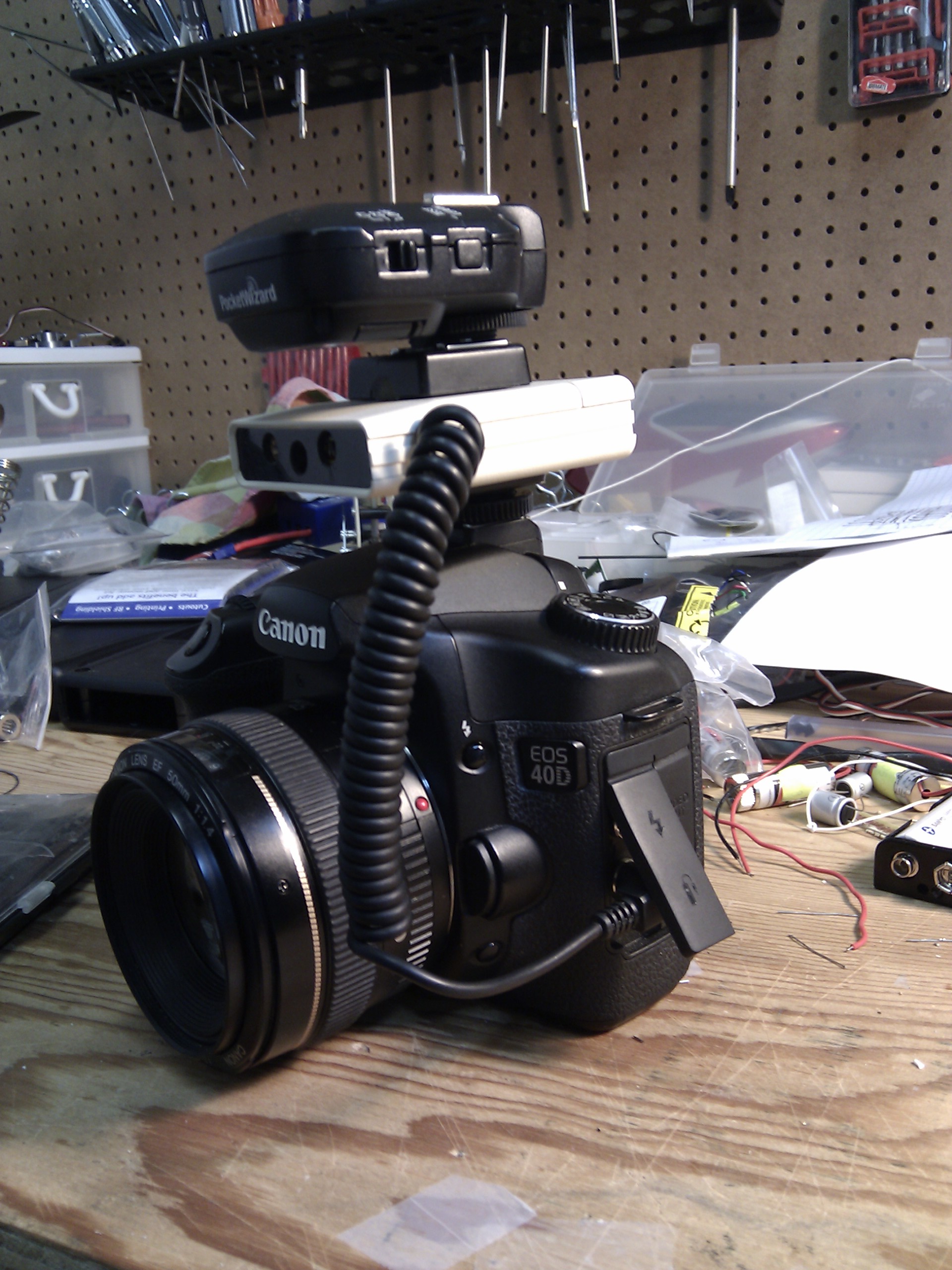
So I did some searching around at local electronics shops and came across a small case that has a battery compartment for one AA battery. Digikey also sells a version of the case in black, which I will grab for the next upgrade. Much sleeker then cream colored on a black camera, though more expensive then the $0.25 I paid for the cream colored cases.
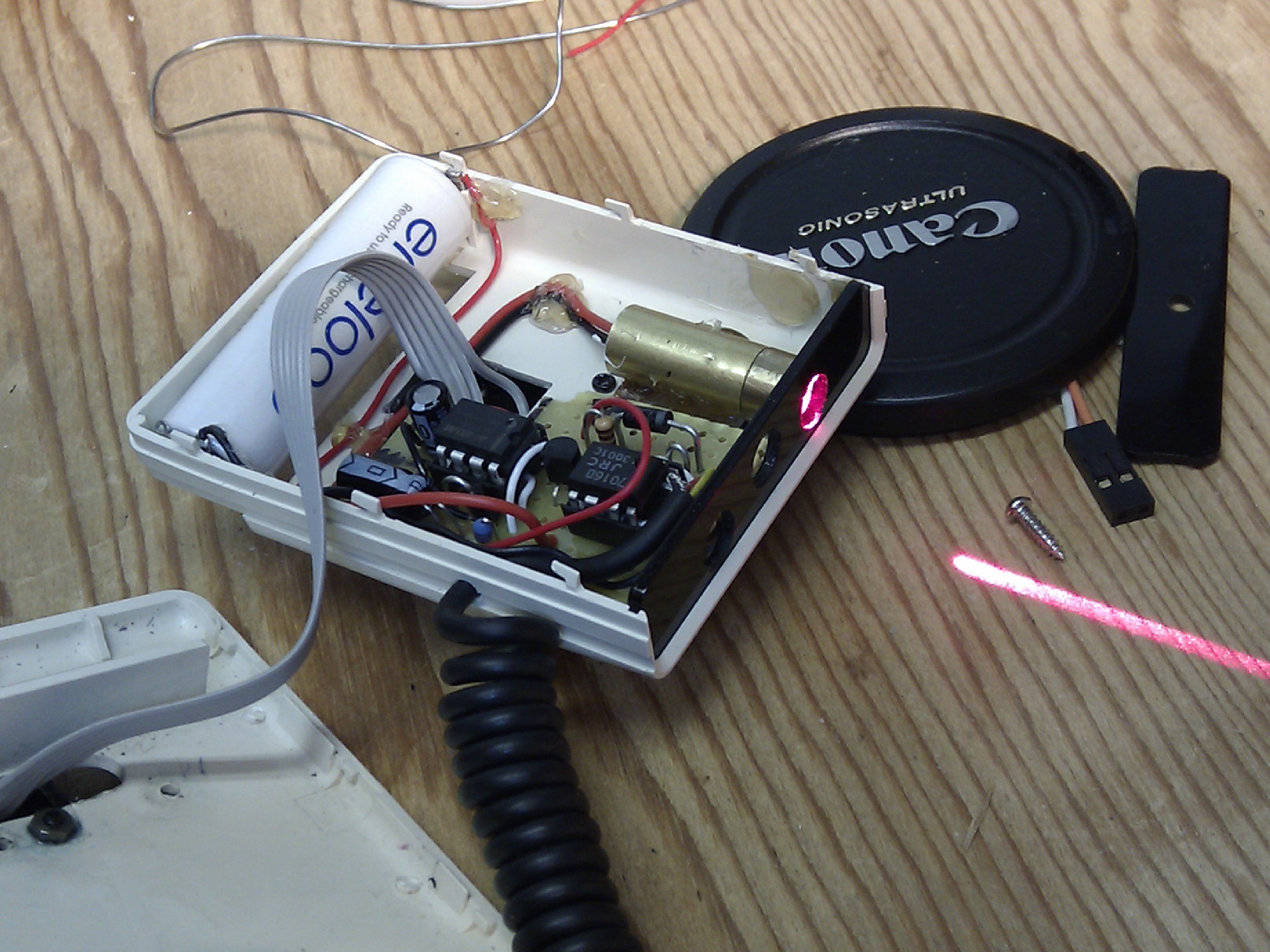
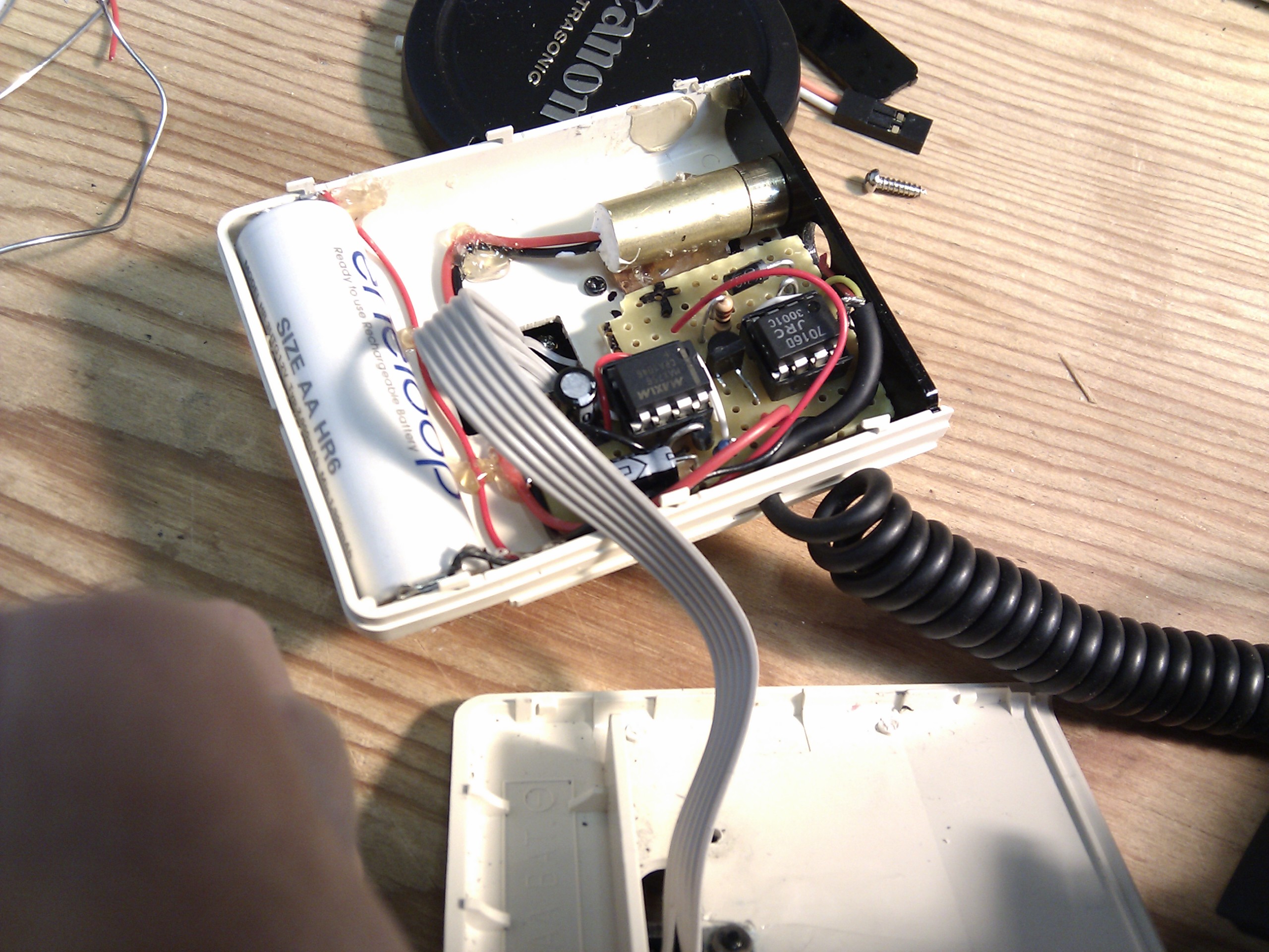
About the same time, i received an order from DealExtreme for some line lasers i had ordered some time ago. So I put together a circuit based on the v3.0 design (plugs in the side of the camera in the remote trigger port) and i have added a dc-dc boost voltage regulator that takes any voltage (0.7volts and higher) and turns it into a constant 3.3volts (based on suggestions from the hack-a-day post comments). This is perfect since that means that regardless of what battery i use, (1.5v alkaline or 1.2v NiMH rechargeable battery) i can get a constant voltage to drive the line laser.
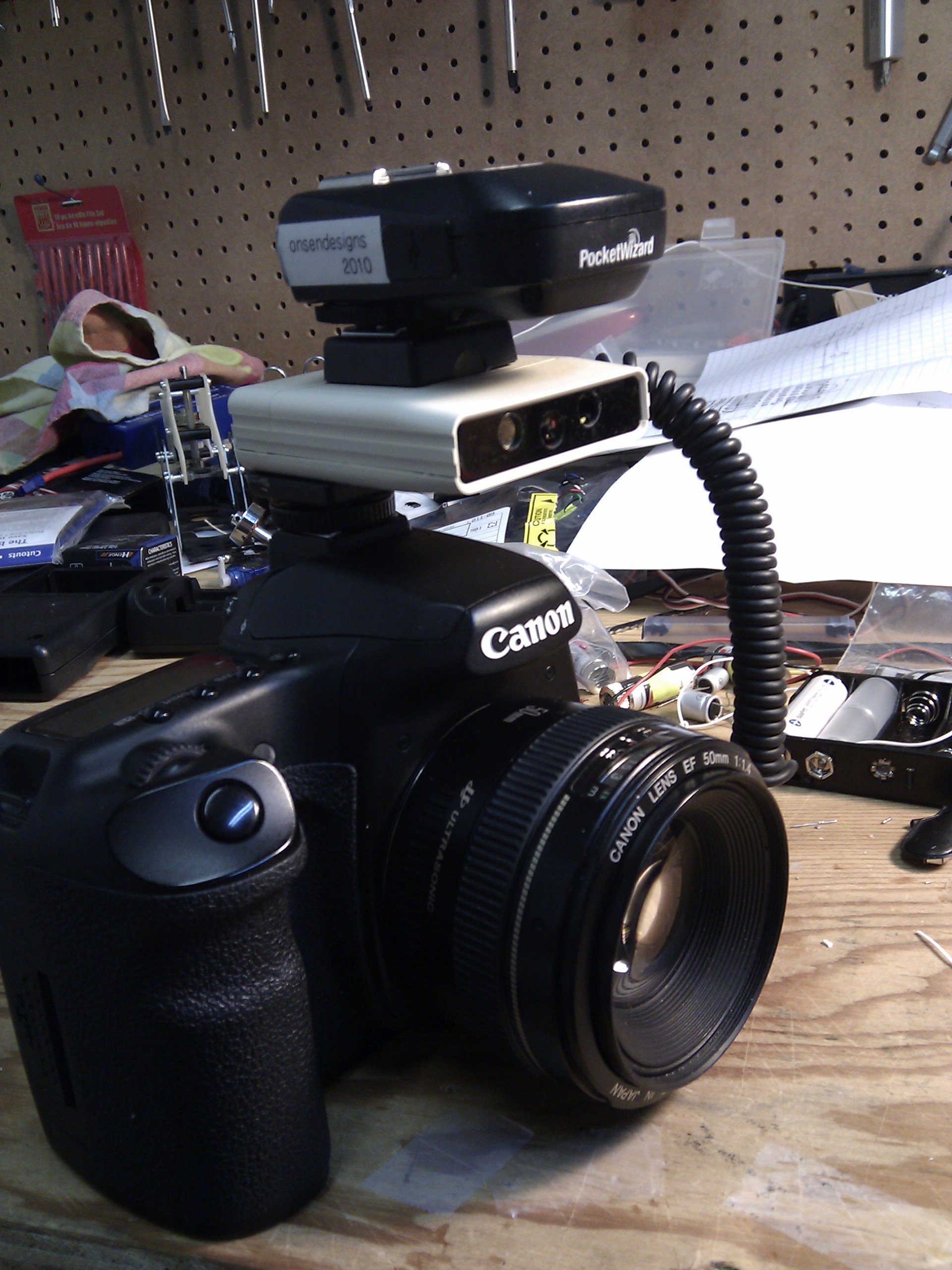
I whipped together a circuit and mounted it inside the small case. But this alone still meant a mess of extra cables. So i added a pass-through ETTL hot shoe connectors, so that I can slide my PW Flex TT1 on top of the AF assistant, and be good to go.
The line laser was aligned vertically, and lined up with the lens, which means that the center focus point (and in landscape mode, the top and bottom AF points get to use the laser line to focus) always has a contrasting line to use to focus on regardless of the subject to camera distance.
 The grey ribbon cable is the E-TTL passthgouth connection. For the hotshoe, I took apart a Yongnuo ETTL Extension Cord and cannibalized the end that sits on the camera. That end has a pass-through. Took that case apart, and used on half of the case on top of my project box, and the other half on the bottom of the box.
There is no electrical connection between the camera hotshoe and my circuit. My circuit is purely driven by the remote shutter release side port on the camera.
Operation

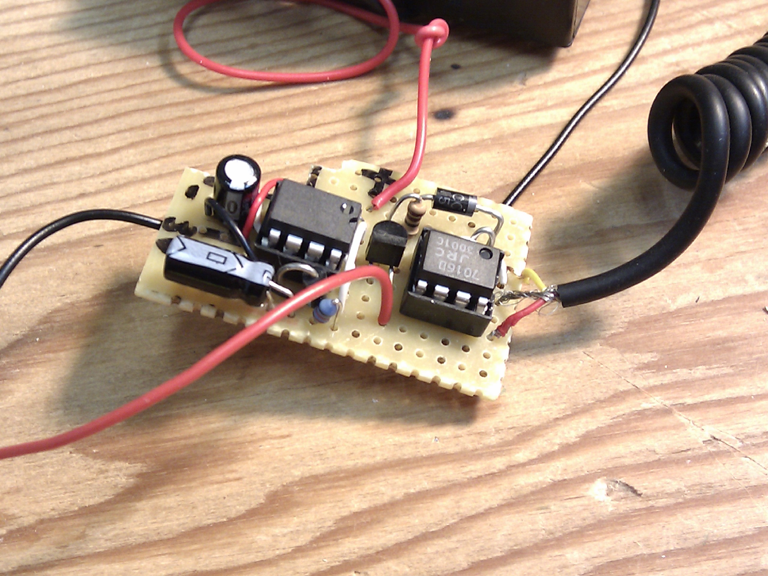
The battery voltage first gets boosted to 3.3V then an op-amp senses the camera voltage and switches a transistor on or off to enable the laser module.
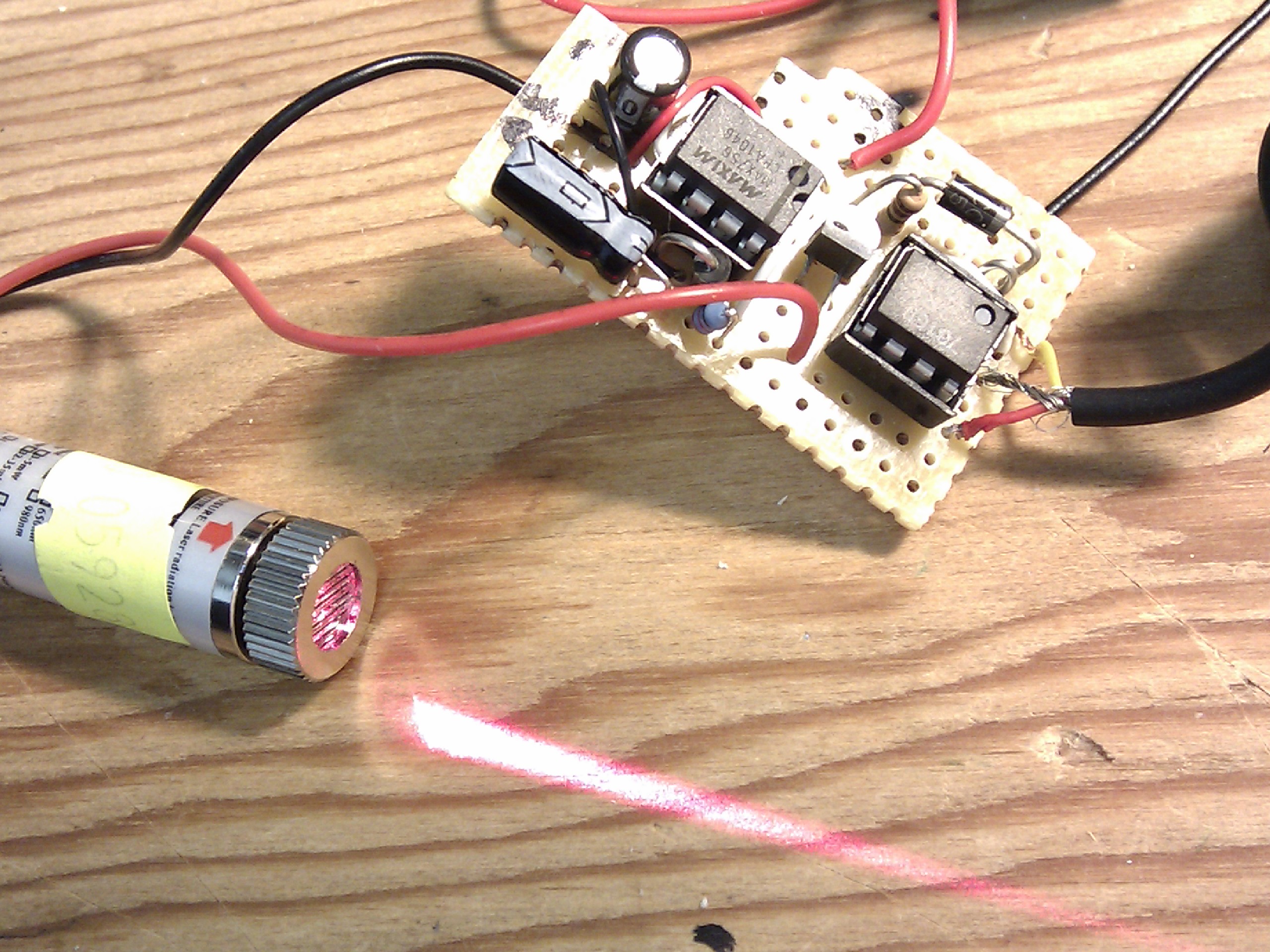
The DC-DC booster circuit is built around the MAX756 IC, which will boost any voltage above 0.7Volts up to either 3.3V or 5V. I choose 3.3V since my laser modules were made for 3V. The battery
The switching of the LED on and off is handled by the same op-amp as in the v3.0 design (the low voltage op-amp NJU7016D), though, a low voltage op-amp is not required (I only used it since it was available); I could have used any other general purpose op-amp that runs on 3V (most do) like a LM358, since the voltage it will see is a regulated 3.3V. The op-amp switches a regular PNP transistor (I used a generic 2N3906) which will conduct when the op-amp input drops to a low state. When the op-amp input goes high, the transistor does not conduct.
The laser is switched off during image capture (full shutter press). This is accomplished by using the ‘shutdown’ pin of the MAX756 IC. When that pin (pin 1) goes to ground, the IC does not boost the voltage, and since the laser does not run at 1.2V or 1.5V, it essentially turns off. The shutter release port’s 3rd pin (the full shutter press) normally has 3.3V on it, which when applied to pin1 of the MAX756, enables it’s operation. When the shutter is fully pressed, that same pin goes to ground, turning off the laser.
Project Photo Gallery
Pingback: AF assist tool v3.0 – complete | adrian's domain
I’ve been reading your posts, and i’m most impressed with your work!!
Question. In the 3.0 version you used the IR LED from a 550ex, which would be MUCH safer to use versus using a laser. You already stated in a previous post how you were at a concert and your laser shows up in other photographers pictures. Why (in version 3.1) would you switch BACK to a laser?
PS I LOVE the look and slim-ness of this case versus the 3.0 version case. Well done!
Well, reason I went away (for the time being) from the IR LED is two-fold.
First, it’s price. The IR LED out of the 550ex flash is about $25 or so. A laser module is about $2.
Second, it’s power requirements. The IR LED draws about 250mA. The laser module draws about 20mA.
I do agree with you in that the IR LED is likely a ‘better’ solution, but I haven’t had the time yet to continue the research on how to make it a viable and cost effective solution.
Just read a few more of your previous posts, its too funny. I too shoot nightclub/bar photography. Focusing in such low light is KEY, and i’m always googling new ideas to achieve it. Your setup in this article:
http://photo.onsendesigns.com/2011/05/neurodance-2-5/
was great! I have had the intention of doing just that so I can get away from shooting my 5d mk2 at 3200+ iso, and not getting so much noise after editing the RAWs. I like to run-and-gun when I cover and event, and a setup like what you did here would very well do the trick!
My only concern is safety. I ABSOLUTELY do not want to jeopardize people’s eyes just to lock on focus. That’s my only appreciation to using lasers.
I saw in another post you are trying different patterns to dispurse and concentrate the contrast of the light better, have you done any research on if it’s possible to turn down the juice enough to what ever is considered the “safe” level of light from the laser?
Well, according to this IEC standard: http://en.wikipedia.org/wiki/File:IEC60825_MPE_W_s.png, 1 mW of visible light per square cm is considered totally safe. You’ll get a lot more intensity than that looking at the laser pointer, but if you spread the beam through some sort of pattern generator and don’t stand too close, the intensity gets pretty safe pretty fast.
If you had, say, a 5mW visible laser with — being really conservative — a 1 sq mm beam at your cornea, you’d have an intensity of 500 mW per sq cm, and you better blink pretty quick. Spread that into a 27 degree fan (the width of your frame with a 50mm-equvalent lens) then at 1 meter you’d generate a 500mm line. That’d conservatively cover 500 sq mm, bringing the intensity down to that safe 1 mW per sq cm. Just don’t stand too close.
Hey, as I was researching external AF assist options, I came across grid projecting lasers.
Check this one out
http://www.youtube.com/watch?v=EGjKK-mdc98
Peter,
Thank you for the video link.
I have not found an optical element to do a proper grid projection.
The problem is that the grid needs to be quite tight so that when the subject is 10-20ft away the grid is still dense enough to have some some lines of contrast where the focus point is.
All the ones I’ve found work great when the subject is close by (and there are lots of lines that fall on the focusing sensor) but as the distance to subject increases, the coarseness of the grid can easily leave the AF point in a ‘dead spot’ on the grid where there’s no lines of high contrast.
I’ve been toying around with building myself something similar. I have an original 5D and the AF is notoriously bad, especially for the club/rave photography I do.
For now, what I opted to do was take a 300EZ that I got for $10 on ebay. Hacked off the strobe circuitry (not as easy as it sounds), and made a TTL pass-through for it. While doing this, I did some other experiments for curiosity sake, such as isolating the signal for the AF lamp right off the shoe pins. I was semi-successfully able to do this – requires a flash to be mounted to the end of the cord, much like Nikon’s SC-29.
This is what I came up with on a breadboard:
– Used a LM324/358 at 5v
– Used an LED for testing on the output.
– D2(top right pin as seen from above) tied to non-inverting input, pulled up to vcc with a 10k resistor.
– ID(bottom right pin as seen from above) tied to inverting input
http://i233.photobucket.com/albums/ee240/efm7/67d7a7dc.jpg
LED mimics the AF illuminator perfectly! This could be the basis for a compact setup for the use with an off-camera flash. (Again, like a Nikon SC-29) It would be great if a circuit can be made to trick the camera into thinking there’s a flash on it, that way it can be used standalone.
I’ll be following your progress on different light sources. I may end up going the remote input route if I feel that the chopped 300EZ is too heavy.